
Equipment

Dredging
Suction dredger extracts the sludge sediments and deliver into processing unit plant
Proccessing Unit
This step consists of inline mixing process and chemical processing unit. The solid in the sludge is flocked.
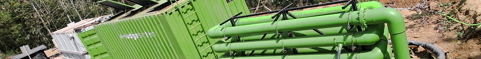
Dewatering Proccess
Processed sludge pumped into the d-sludge tube where solids and water are separated.
Disposal
If needed, the containers can be disposed at a landfill or the solids removed and used elsewhere

d-sludge tube dewatering system starts from pumping processed sludge into the d-sludge tube and in this tube is where the separation between solids and water occurs. With the geotextile’s ability to hold particles, the solids will be left behind and settle in the d-sludge tube and the water can flow out due to the permeability of the geotextile material. To increase the dewatering capacity and improve sludge drying performance there are two basic physical bonds or agglomeration principles used, namely coagulation and flocculation. The latter is the most commonly used one together with geotextile dewatering tube.
The main system components required for operation consist of :

d-sludge tube

Flocculator

Dissolver, dosing unit, pump, etc

Dewatering Process Area